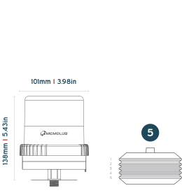
Memolub Connect Pro Tech Specs

MEMOLUB CONNECT SERIES KNOWLEDGE BASE

WIRELESS CONTROL

LEARNING PERIOD

The Memolub Connect Pro are equipped with advanced machine learning capabilities, allowing it to account for environmental conditions when calculating its status. A learning period of 20 cycles is required, during which the lubricator must remain in the same environment without any changes to its position, fastening, support, or grease type. If any of these parameters are altered, the learning process can be reset by pressing and holding the pushbutton for more than 5 seconds.

INSTALLATION GUIDELINES

DIRECT INSTALLATION

  • 1

    B1

    Prime lube point and remove nipple.

  • 2

    B2

    Install VISIO Base using a strong threadlocker (BSP 1/4).

  • 3

    B3

    With setting key, choose wheel position according to "Settings" table above.

  • 4

    B4

    Align the pin of VISIO Module with the notch of VISIO Base.

  • 5

    B5

    Screw tightly keeping the assemly aligned.

  • 6

    B6

    VISIO initializes, flashes each color on, and makes one expulsion. Green lights confirm normal operation.

  • 1

    B1

    Prime lube point and remove nipple.

  • 2

    B2

    Install VISIO Base using a strong threadlocker (BSP 1/4).

  • 3

    B3

    With setting key, choose wheel position according to "Settings" table above.

  • 4

    B4

    Align the pin of VISIO Module with the notch of VISIO Base.

  • 5

    B5

    Screw tightly keeping the assemly aligned.

  • 6

    B6

    VISIO initializes, flashes each color on, and makes one expulsion. Green lights confirm normal operation.

REMOTE INSTALLATION

  • 1

    C1

    Prime lube point and remove nipple.

  • 2

    C2

    Secure the mounting bracket.

  • 3

    C3

    Install VISIO Base and F1/4 fitting on bracket using a strong threadlocker.

  • 4

    C4

    Install BSP 1/8 fitting on lube point.

  • 5

    C5

    Cut hose to required size.

  • 6

    C6

    Insert hose into bracket's quick fitting.

  • 7

    C7

    Insert hose into lube point's quick fitting.

  • 8

    C8

    With setting key, choose wheel position according to "Settings" table above.

  • 9

    C9

    Align the pin of VISIO Module with the notch of VISIO Base.

  • 10

    C10

    Screw tightly keeping the assembly aligned.

  • 11

    C12

    VISIO initializes, flashes each color on, and makes one expulsion. Green lights confirm normal operation.

  • 1

    C1

    Prime lube point and remove nipple.

  • 2

    C2

    Secure the mounting bracket.

  • 3

    C3

    Install VISIO Base and F1/4 fitting on bracket using a strong threadlocker.

  • 4

    C4

    Install BSP 1/8 fitting on lube point.

  • 5

    C5

    Cut hose to required size.

  • 6

    C6

    Insert hose into bracket's quick fitting.

  • 7

    C7

    Insert hose into lube point's quick fitting.

  • 8

    C8

    With setting key, choose wheel position according to "Settings" table above.

  • 9

    C9

    Align the pin of VISIO Module with the notch of VISIO Base.

  • 10

    C10

    Screw tightly keeping the assembly aligned.

  • 11

    C12

    VISIO initializes, flashes each color on, and makes one expulsion. Green lights confirm normal operation.

MULTIPOINT INSTALLATION

  • 1

    D1

    Prime lube point and remove nipple.

  • 2

    D2

    Secure the mounting bracket.

  • 3

    D3

    Install VISIO Base and F1/4 fitting on bracket using a strong threadlocker.

  • 4

    D4

    Install BSP 1/8 fitting on lube point.

  • 5

    D5

    Cut the hoses to required size.

  • 6

    D6

    Insert hoses into bracket's quick fittings.

  • 7

    D7

    Insert hoses into lube points' quick fittings.

  • 8

    D8

    With setting key, choose wheel position according to "Settings" table above.

  • 9

    D9

    Align the pin of VISIO Module with the notch of VISIO Base.

  • 10

    D10

    Screw tightly keeping the assembly aligned.

  • 11

    D12

    VISIO initializes, flashes each color on, and makes one expulsion. Green lights confirm normal operation.

  • 1

    D1

    Prime lube point and remove nipple.

  • 2

    D2

    Secure the mounting bracket.

  • 3

    D3

    Install VISIO Base and F1/4 fitting on bracket using a strong threadlocker.

  • 4

    D4

    Install BSP 1/8 fitting on lube point.

  • 5

    D5

    Cut the hoses to required size.

  • 6

    D6

    Insert hoses into bracket's quick fittings.

  • 7

    D7

    Insert hoses into lube points' quick fittings.

  • 8

    D8

    With setting key, choose wheel position according to "Settings" table above.

  • 9

    D9

    Align the pin of VISIO Module with the notch of VISIO Base.

  • 10

    D10

    Screw tightly keeping the assembly aligned.

  • 11

    D12

    VISIO initializes, flashes each color on, and makes one expulsion. Green lights confirm normal operation.

PUSH BUTTON

TEST YOUR MEMOLUB / FORCE EXPULSION

  • 1

    E2

    Locate the push button on the bottom of the memo

  • 2

    E2

    Push the button

  • 3

    E4

    VISIO initializes, flashing each color on successively.

  • 4

    E5

    VISIO makes 1 expulsion.

  • 5

    E6

    After scanning all parameters, VISIO flashes green lights in case of normal operation. For any other colors, please refer to the FAQ section.

  • 1

    E2

    Locate the push button on the bottom of the memo

  • 2

    E2

    Push the button

  • 3

    E4

    VISIO initializes, flashing each color on successively.

  • 4

    E5

    VISIO makes 1 expulsion.

  • 5

    E6

    After scanning all parameters, VISIO flashes green lights in case of normal operation. For any other colors, please refer to the FAQ section.

CARTRIDGE (RE)PLACEMENT GUIDELINES

  • 1

    A1

    Remove VISIO Module from VISIO Base.

  • 2

    A2

    Open VISIO Module (fingers on ribs). Remove the used cartridge, if any.

  • 3

    A3

    Prime VISIO Pump.

  • 4

    A4

    Insert new battery pack and seal. NOTE: the battery seal can be removed for 480cc cartridges

  • 5

    A5

    Squeeze air out of the cartridge.

  • 6

    A6

    Replace the cartridge on VISIO Pump.

  • 7

    A7

    Close and lock VISIO Module (fingers on ribs).

  • 8

    A8

    Align the pin of VISIO Module with the notch of VISIO Base.

  • 9

    A9

    Screw tightly keeping the assembly aligned.

  • 10

    A10

    VISIO initializes, flashes each color on, and makes one expulsion. Green light confirms proper functioning.

  • 1

    A1

    Remove VISIO Module from VISIO Base.

  • 2

    A2

    Open VISIO Module (fingers on ribs). Remove the used cartridge, if any.

  • 3

    A3

    Prime VISIO Pump.

  • 4

    A4

    Insert new battery pack and seal. NOTE: the battery seal can be removed for 480cc cartridges

  • 5

    A5

    Squeeze air out of the cartridge.

  • 6

    A6

    Replace the cartridge on VISIO Pump.

  • 7

    A7

    Close and lock VISIO Module (fingers on ribs).

  • 8

    A8

    Align the pin of VISIO Module with the notch of VISIO Base.

  • 9

    A9

    Screw tightly keeping the assembly aligned.

  • 10

    A10

    VISIO initializes, flashes each color on, and makes one expulsion. Green light confirms proper functioning.

EXTERNAL POWER CONNECTION

INSTALLING THE CONNECTOR (CONNECT PRO ONLY)

  • 1

    Visio E Pconnector Installation1

    Locate the M4 set screw on the CONNECT PRO BASE rotary coupling. Screw it tightly.

  • 2

    Visio E Pconnector Installation2bis

    Screw tightly the CONNECT PRO pump & base on the bracket elbow

  • 3

    Visio E Pconnector Installation3

    Release the rotary coupling by unscrewing the M4 screw.

  • 4

    Visio E Pconnector Installation4

    Rotate the CONNECT PRO pump & base assembly clockwise, until the connector socket is outside the bracket.

  • 5

    Visio E Pconnector Installation5

    Check that the cable plug can engage properly on the connector socket

  • 6

    Visio E Pconnector Installation6

    Keeping the plug engaged, secure the M4 set screw tightly.

  • 7

    Visio E Pconnector Installation7

    The rotary coupling is now set. When disassembling/reassembling pump and base for maintenance pruposes, the connector will always find the same place.

  • 1

    Visio E Pconnector Installation1

    Locate the M4 set screw on the CONNECT PRO BASE rotary coupling. Screw it tightly.

  • 2

    Visio E Pconnector Installation2bis

    Screw tightly the CONNECT PRO pump & base on the bracket elbow

  • 3

    Visio E Pconnector Installation3

    Release the rotary coupling by unscrewing the M4 screw.

  • 4

    Visio E Pconnector Installation4

    Rotate the CONNECT PRO pump & base assembly clockwise, until the connector socket is outside the bracket.

  • 5

    Visio E Pconnector Installation5

    Check that the cable plug can engage properly on the connector socket

  • 6

    Visio E Pconnector Installation6

    Keeping the plug engaged, secure the M4 set screw tightly.

  • 7

    Visio E Pconnector Installation7

    The rotary coupling is now set. When disassembling/reassembling pump and base for maintenance pruposes, the connector will always find the same place.

REMOTE CONTROL

INTERMITTENT MODE

MEMOLUB VISIO PRO

DESCRIPTION SIGNAL
INPUT SIGNAL (FROM CUSTOMER PLC/TIMER)
OUTPUT SIGNAL "BUSY" (TO CUSTOMER PLC)
PUMP OUTLET (TO LUBRICATION)
OUTPUT SIGNAL "DEFAULT" (TO CUSTOMER PLC)

CONTINUOUS MODE

MEMOLUB VISIO PRO

DESCRIPTION SIGNAL
INPUT SIGNAL (FROM CUSTOMER PLC/TIMER)
OUTPUT SIGNAL "BUSY" (TO CUSTOMER PLC)
PUMP OUTLET (TO LUBRICATION)
OUTPUT SIGNAL "DEFAULT" (TO CUSTOMER PLC)

CLOUD INTERFACE

Memolub IOT Home

Platform home

The platform home screen welcomes the user and provides an entry point into the connected device fleet. From here, users navigate to their assigned sites and device groups via the left-hand panel.

Memolub IOT Lubricator Overview

Device overview

The device overview lists all connected units within a site, showing key identifiers such as Memolub ID, location name, lubricant type, cartridge volume, and lubrication frequency. A map view below the list displays the geographic position of all installed units, giving operators an immediate picture of their installation footprint.

Memolub IOT Lubricator Settings

Lubricator Dashboard

The device dashboard provides a full status overview of a single unit, including real-time readings for temperature, battery level, mechanical condition, lubrication flow, and remaining cartridge volume. Device configuration and alarm thresholds are accessible and adjustable directly from this screen. Three remote commands are available: Force Expulsion, Find Me, and Reset Volume.

Memolub IOT Lubricator Alerts

Alarm and event log

The alarm screen logs all alarm events for the selected device, showing appearance and disappearance timestamps for each triggered condition. An event occurrence table alongside it summarises trigger sources and their frequency over a user-defined time period, supporting trend analysis and maintenance planning.

Memolub IOT Lubricator Settings

Settings and alarm thresholds

The settings view exposes sensor parameters and configurable alarm thresholds in a single screen. Thresholds cover cartridge volume, battery level, and temperature, each with warning and critical levels. All settings are adjustable remotely via the platform.

Memolub IOT Lubricator Report

Reports

The report screen presents cartridge volume, battery level, and temperature as separate time-series charts over a user-defined period. Each chart plots the measured value against its configured alarm threshold, giving operators a clear visual reference for how device performance compares to set limits over time.

FAQ

  • Nothing happens after screwing the module on the base.

    • The pin of the module is possibly not proper aligned with the notch of the base. Unscrew the module from the base, align correctly and screw it again.
    • VISIO Module is not tightly screwed to VISIO Base. Turn it clockwise until stop.
    • There is possibly no battery inside the module. Insert 3x 1,5 VDC AA batteries to resolve the issue.
    • There is possibly something obstructing the communication between the base and the module contacts. Unscrew the module from the base, remove any dust or obstacles from the base and the module contacts and screw back together tightly.
  • The touchpad does not work after initialisation was completed successfully.

    Your MEMOLUB® VISIO possibly initialized in an unstable environment. Unscrew the base from the module and screw again to reset the system. Wait until one expulsion is performed and you observe green lights, indicating the initialization is complete.

  • The red lights are blinking periodically.

    • There is possibly a too high back pressure present in the system. Inspect your downstream piping to remove any clogging or jam. Activate the touchpad and check for at least 2 expulsions if the systems operate fine.
    • There is possibly something obstructing the communication between the base and the module contacts. Unscrew the module from the base, remove any dust or obstacles from the base and the module contacts and screw back together tightly.
    • The motor is broken. Replacement of the module is necessary.
  • The yellow lights are blinking periodically.

    • There is possibly something obstructing the communication between the base and the module contacts. Unscrew the module from the base, remove any dust or obstacles from the base and the module contacts and screw back together tightly.
    • The batteries are empty. Replacement of the battery pack is necessary.
  • The blue lights are blinking periodically.

    • The cartridge is possibly out of grease. Replacement of the cartridge is necessary.
    • The system is not primed. Prime the system using a manual grease pump.
    • The system is operating out of its minimum and maximum temperature range. Please make sure the system is operating within the recommended temperature range.

VIDEO'S

REGULATORY INFORMATION

SYMBOL DESCRIPTION
This product is compliant with Directives 2006/42/EC (Machinery). The relevant Declaration of Conformity is available here.
This product is compliant with UK regulations 2008 No. 1597 (Supply of Machinery). The relevant Declaration of Conformity is available here.
This product is compliant with customs union technical regulation TR CU 010/2011 (safety of machines and equipment). The relevant Declaration of Conformity is available here.
The WEEE symbol is attached to the product in compliance with the EU directive 2012/19/EU on Waste Electrical and Electronic Equipment (WEEE). It is intended to deter the improper disposal of this product and to promote reuse and recycling.
The packaging material can be recycled. Please arrange for the environmental appropriate disposal of the packaging.